LAN NAT
flexiWAN supports LAN NAT configuration for 1:1 NAT or NAPT (Network Address and Port Translation). This feature is particularly useful for multi-site deployments where customers use the same LAN IP subnet across various locations. LAN NAT translate the LAN addresses to a unique set of addresses while traversing the network.
The LAN 1:1 NAT feature in flexiWAN facilitates Source and Destination Network Address Translation (SDNAT) specifically tailored for local area network (LAN) interfaces. LAN NAT is a type of NAT in which both the source and/or destination IP addresses of a packet are changed as it traverses a network. This can be used to rewrite the destination address of incoming packets to direct them to the correct internal device, while simultaneously rewriting the source address to ensure that reply packets are sent back to the correct external device.
In addition to LAN 1:1 NAT, flexiWAN also supports LAN NAPT. LAN NAPT extends the 1:1 NAT functionality by allowing an entire LAN subnet to be NAT-ed to one or more configured NAT IP addresses. It functions as a Many-to-1 NAT, enabling multiple devices on a LAN to share a single or several NAT IP addresses. By NAT-ing the LAN traffic to unique external NAT IP addresses per site, LAN NAPT ensures there are no IP conflicts while maintaining consistent network architecture across sites.
Getting started
LAN NAT, or Local Area Network Network Address Translation, is a specific implementation of SDNAT (Source and Destination Network Address Translation) that works exclusively on LAN-based network interfaces. It modifies both the source and destination IP addresses of packets as they traverse through a network, ensuring optimal routing and delivery of data within a LAN environment. By changing both the source and destination addresses, LAN NAT allows for improved flexibility and control in managing internal network traffic, providing an efficient means of routing data packets within a local area network. LAN NAT allows to use the same LAN subnet across devices while using unique NATted address.
Configuring LAN NAT 1:1
To configure LAN NAT, navigate to device settings and from the Configuration tab click on Firewall & NAT. From there click on + sign under LAN NAT.
LAN NAT configuration window will open, see below for details of each section.
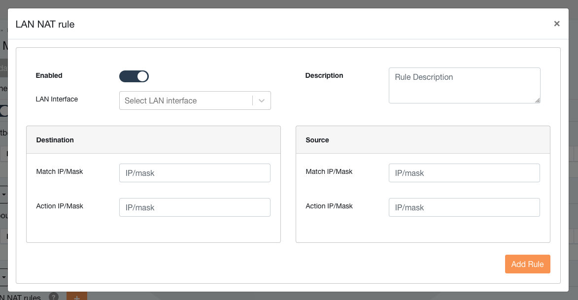
The window shows two sections, source and destination.
Source
Match IP/Mask - used to mark source IP, from where the traffic is originating.
Action IP/Mask - once configured, source Match IP will be translated to Action IP.
LAN Interface - select interface for this specific rule. Used in case there are multiple LAN interfaces.
Destination
Match IP/Mask - used for setting remote / destination IP which source network / client is accessing.
Action IP/Mask - actual IP to which the traffic from Match IP translates.
Depending on the use case, configuration of both sections is not obligatory always. In order to understand how LAN NAT feaute is used, two use cases are prepared below:
Rewriting destination IP address
Communication between overlapping LAN range
Configuring LAN NAPT
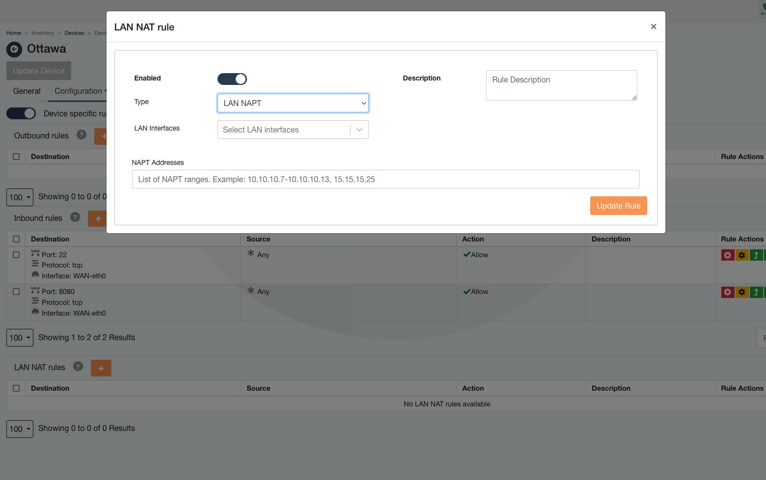
To configure LAN NAPT on flexiWAN, the process is similar to configuring LAN NAT 1:1 with some key differences. Navigate to the LAN NAT Rule Settings, just as with LAN NAT 1:1. Click on the + sign to add a new LAN NAT rule.
In the Type dropdown, select LAN NAPT. This specifies that the rule will use the Network Address and Port Translation method instead of 1:1 NAT.
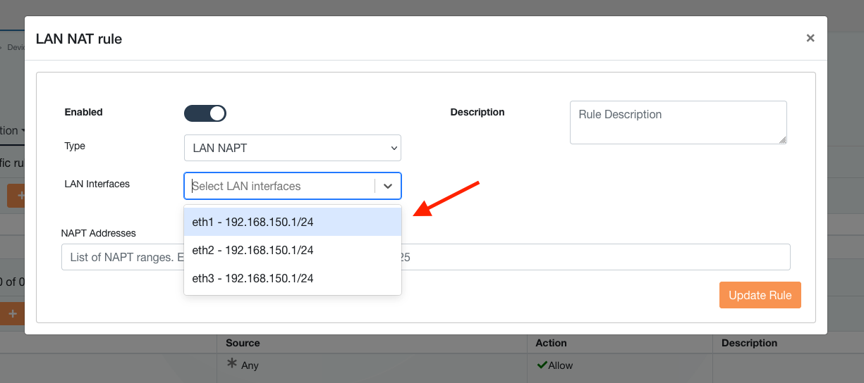
In the LAN Interfaces dropdown, select the LAN interface(s) that this rule will apply to. These are the internal network interfaces whose traffic will be translated using NAPT.
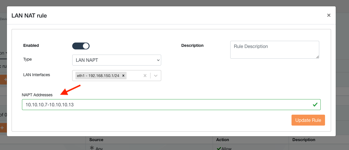
In the NAPT Addresses field, specify the range of NAT IP addresses that will be used to translate the LAN traffic. For instance, you might define a range such as 10.10.10.7-10.10.10.13 or individual addresses like 15.15.15.25. This allows the entire LAN subnet to be NAT-ed to one or more external IP addresses, creating the Many-to-1 NAT scenario as described.
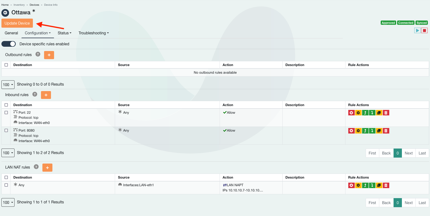
Once all fields are configured, click the Update Rule button to save the configuration. The rule will now be active, translating all traffic from the specified LAN interfaces using the provided NAT IP range.
Use cases
The following use cases are tested and supported by flexiWAN, however many other use cases are possible.
Rewriting destination IP
In a network configuration comprising multiple branch offices (spokes) connected to a central hub, each spoke utilizes an identical LAN IP range of 192.168.130.0/24. The hub operates on a distinct LAN IP range of 192.168.132.0/24, hosting a main server with the actual IP address of 192.168.132.100/32. Spoke LAN clients / devices are configured to communicate with this server via a designated virtual IP address of 200.8.8.1/32. This IP cannot be changed and is hardcoded at the clients, which is common use case in industrial devices, ATMs etc.
For this use case, two devices are prepared with the following networking configuration:
Ottawa - Spoke - LAN range 192.168.130.0/24
Madrid - Hub - LAN range 192.168.132.0/24
Madrid - Server - LAN IP 192.168.132.100/32
Hardcoded server IP at Ottawa LAN clients - 200.8.8.1/32
The LAN NAT feature on flexiWAN addresses the challenge of this uniform IP schema across the branches. It allows network administrators to implement rules that match the source IP from the spoke clients with the pre-configured destination IP and seamlessly redirect this traffic to the main server’s actual IP address at the hub. This scenario exemplifies how LAN NAT facilitates communications between similarly addressed LANs across a hub-and-spoke topology without the need for reconfiguration at each endpoint.
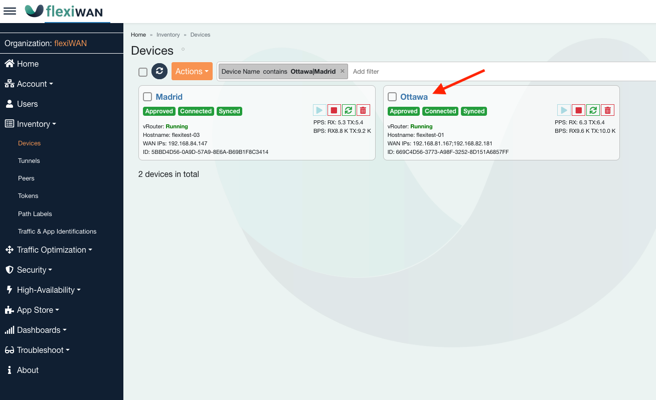
To configure this use case, navigate to the Devices page. In this example, Ottawa is spoke site while Madrid is spoke. Click on the Ottawa edge.
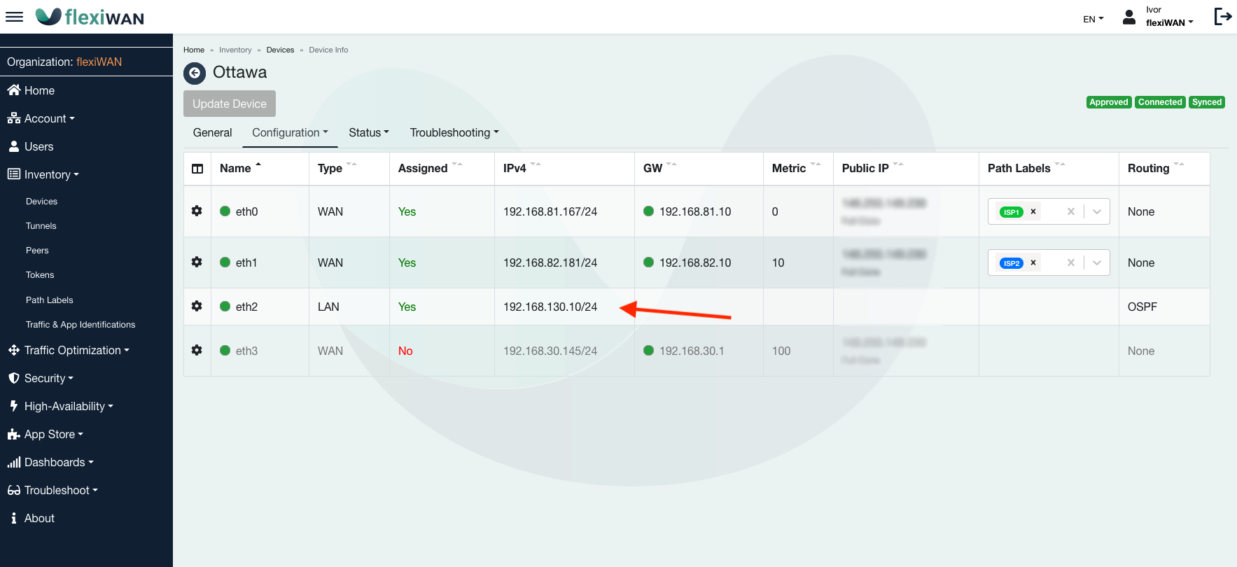
From the interfaces page, observe LAN IP and its range of 192.168.130.0/24
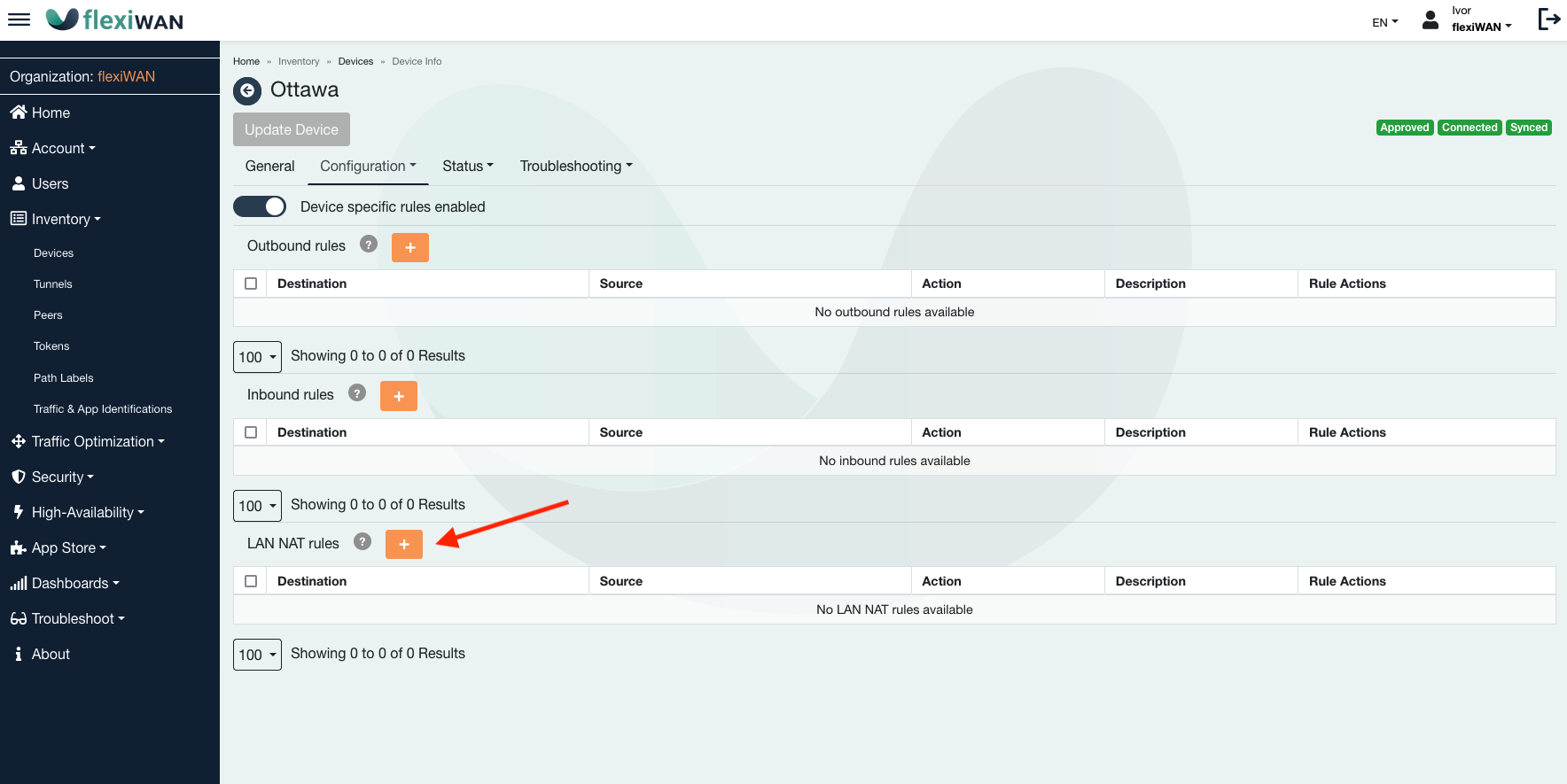
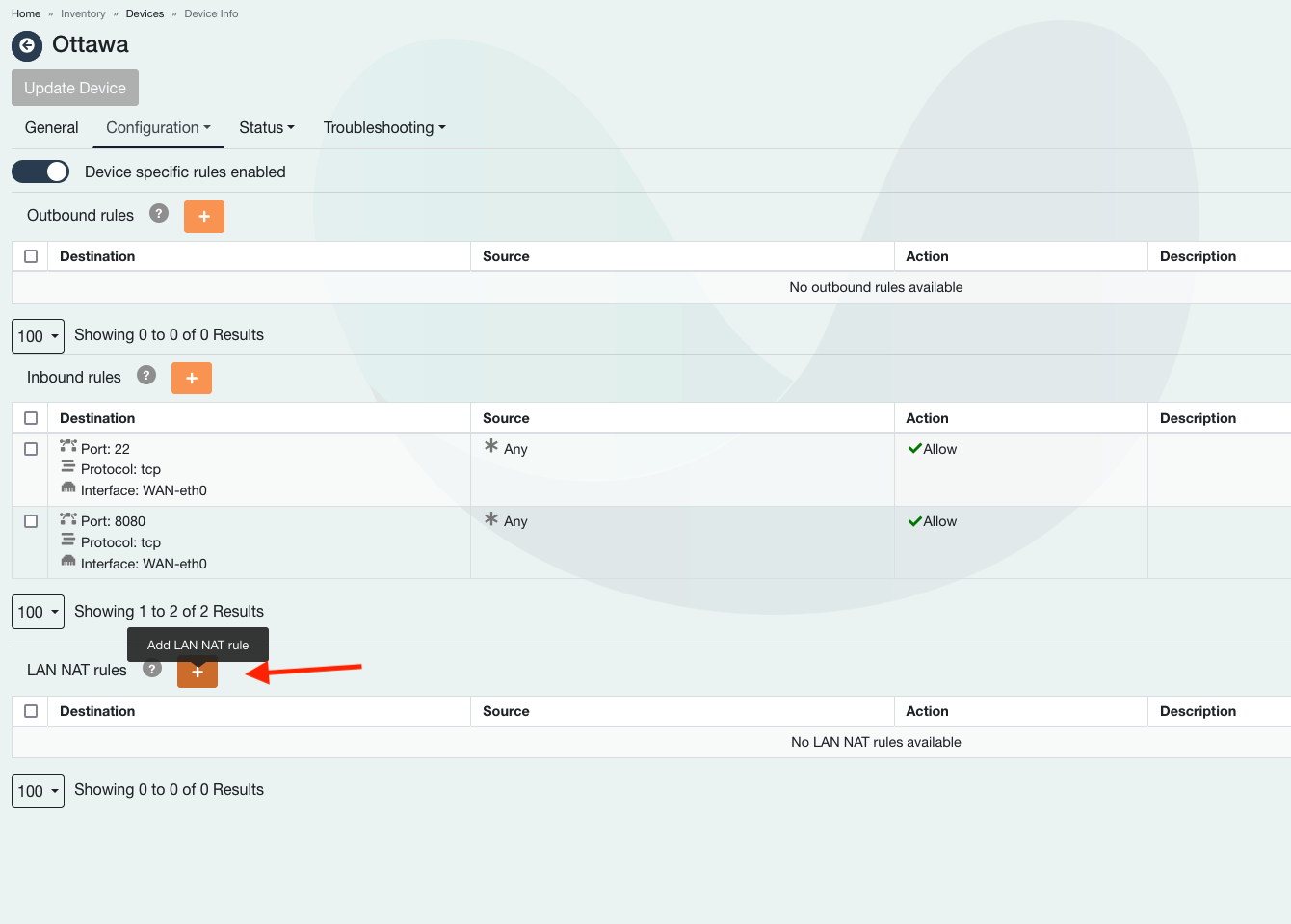
Navigate to Configuration > Firewall & NAT. Click on the + sign under LAN NAT rules to add a new rule.
In the following section, configure the IP’s as in screenshot to match the source IP from the spoke clients with destination IP and redirect its traffic to the main server’s actual IP address at the hub, which is in this case 192.168.132.100/32. See below screenshot for more details.
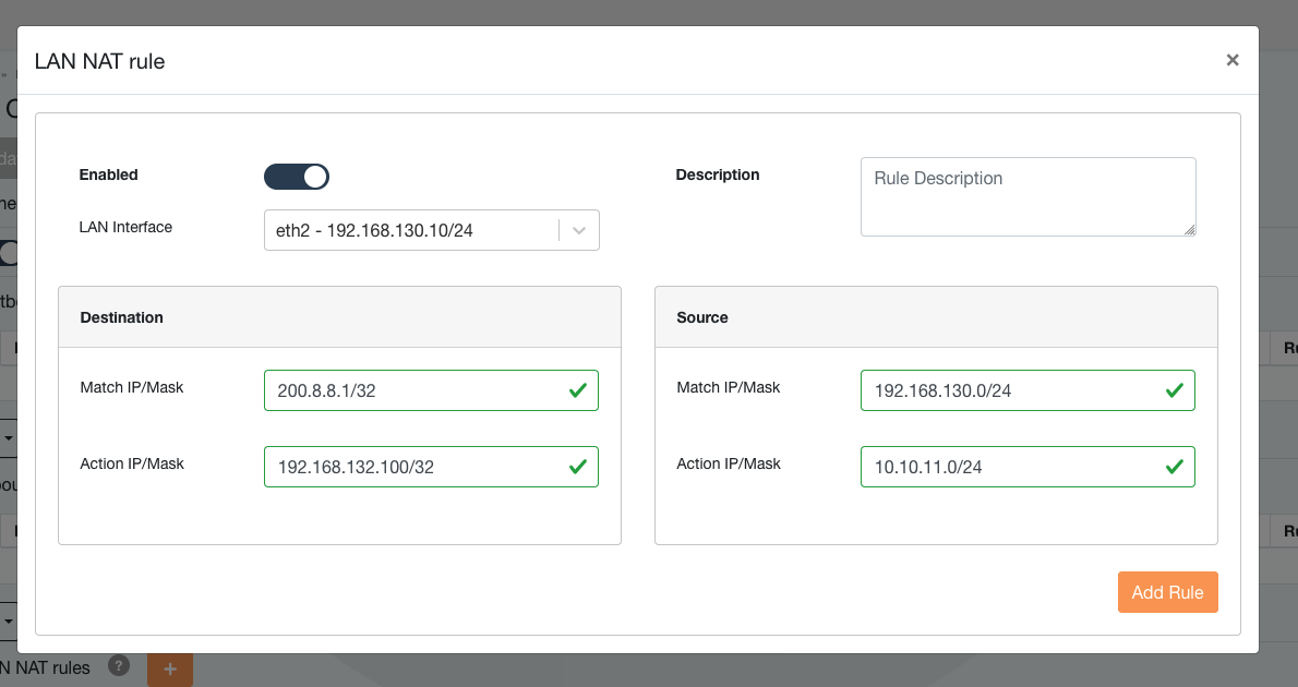
The screenshot above shows the following:
LAN Interface: Make sure to select LAN
Source - Match IP/Mask: from where traffic will be originating, 192.168.130.0/24.
Source - Action IP/Mask: IP range from which the remote hub end will see traffic arriving from, 10.10.11.0/24.
Destination - Match IP/Mask: IP which LAN clients have hardcoded to access resources from, 200.8.8.1/32
Destination - Action IP/Mask: Actual IP to which the matched IP will be translated to, 192.168.132.100/32
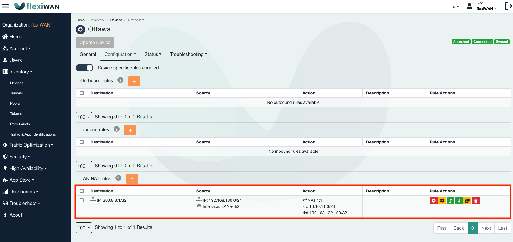
Confirm everything is correctly configured.
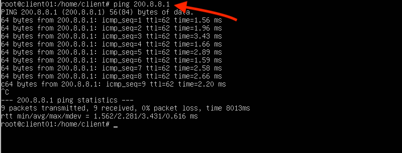
Now its time to test the configuration. From the LAN client, attempt to access the remote server resource using its IP 200.8.8.1. As screenshot shows, remote IP is responding.
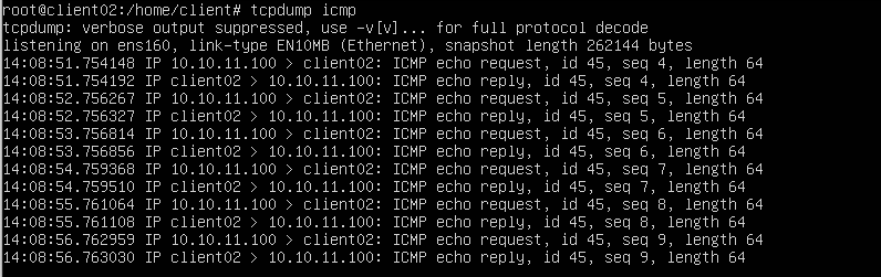
On the other end, running tcpdump on LAN client of IP 192.168.132.100 confirms traffic from spoke is arriving and from its IP 10.10.11.100. This IP range was set in the LAN NAT rule configuration.
Communication between overlapping LAN ranges
In this scenario, multiple flexiEdge locations are established in a full mesh topology, each with LANs configured identically using the IP range of 192.168.130.0/24. Given that flexiWAN employs OSPF for network routes propagation between sites, direct communication between LAN clients with duplicate IP ranges is not possible out-of-the-box. This use case demonstrates how the LAN NAT feature resolves this challenge by enabling configurations that facilitate inter-site communication, despite the identical LAN configurations. Through LAN NAT, source traffic from these overlapping networks is selectively matched and rerouted to a unique range, ensuring seamless connectivity across the meshed network.
For this use case, two devices are prepared with the following networking configuration:
Ottawa - LAN IP 192.168.130.10/24
Madrid - LAN IP 192.168.130.20/24
Both devices have DHCP server enabled serving IP’s from the set LAN range.
LAN client is connected at each end. Both LAN clients have an IP 192.168.130.100/32
The aim is to establish communication across multiple sites with identical LAN IP ranges, including cases where the same LAN client IP addresses are in use. To achive this, each site will configure transit IP range
Ottawa - 10.10.11.0/24
Madrid - 10.10.10.0/24
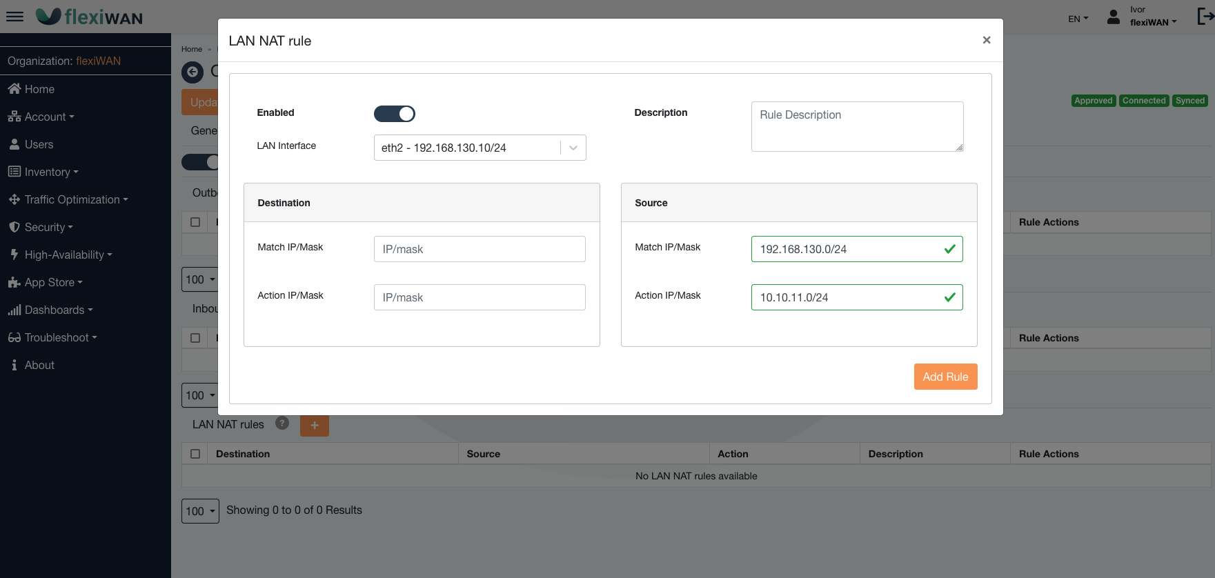
For this configuration, proceed to the Devices page, select the settings for the Ottawa device. From the Configuration tab, access Firewall & NAT and hit the plus (+) icon in the LAN NAT section. As seen in the screenshot below, the ‘Match IP’ is set as 192.168.130.0/24 and the ‘Action IP’ as 10.10.11.0/24, indicating that outgoing traffic from the 192.168.130.0/24 network will be converted to the 10.10.11.0/24 network.
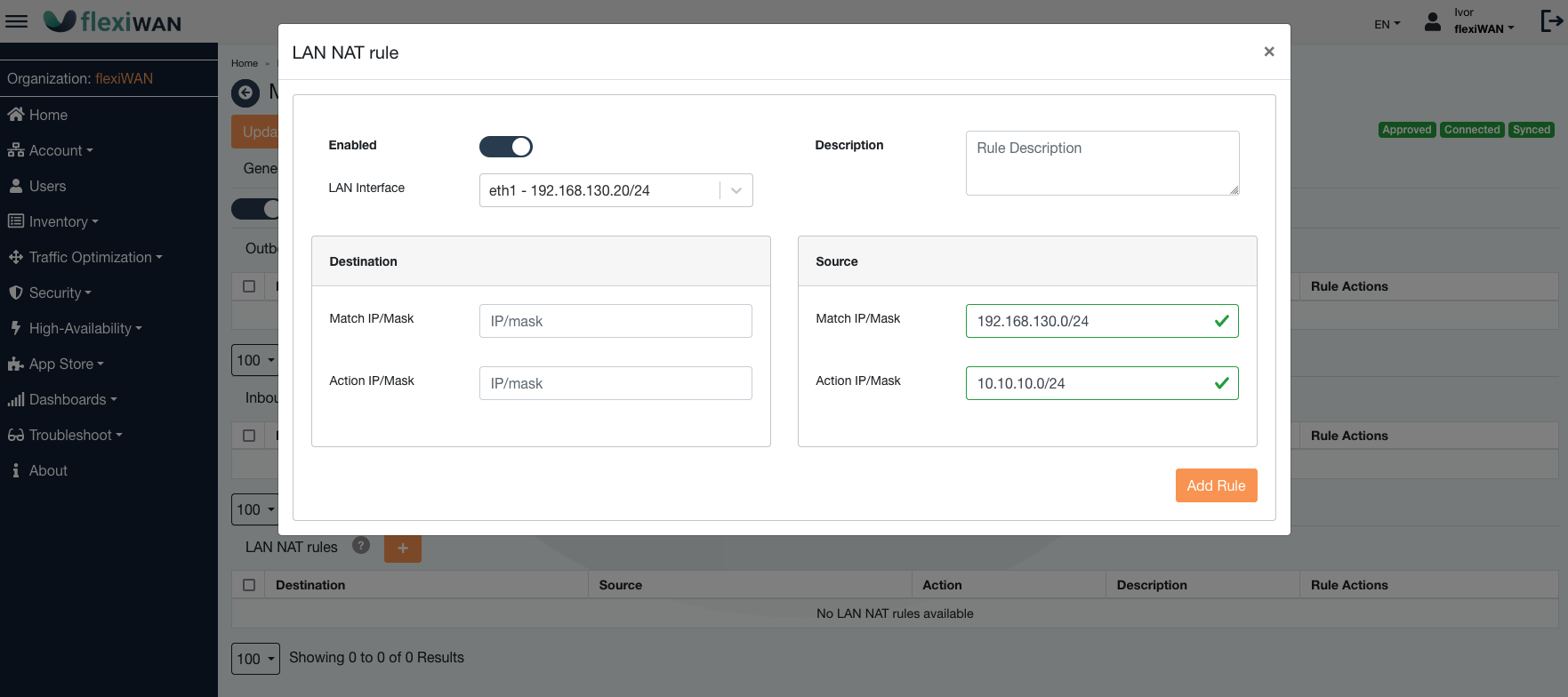
After setting up LAN NAT on the initial device, it’s crucial to carry out the same steps for the corresponding device at the other location, here referred to as the Madrid device. Go to its Firewall & NAT settings and establish a new LAN NAT rule. In the provided screenshot, the source ‘Match’ is again 192.168.130.0/24, similar to the first device. However, the ‘Action IP’ differs; on the Madrid device, it’s assigned to the 10.10.10.0/24 network.
Once both edges are configured, its time to test the configured rules. The following points are important to note:
The action IP’s on both edges will be used for inter-edge communication, instead of their actual IP’s from 192.168.130.0/24 range.
LAN client from Ottawa edge has an IP of 192.168.130.100, so LAN client from Madrid site must use 10.10.11.100 to reach it.
LAN client from Madrid edge has an IP of 192.168.130.100, so LAN client from Ottawa edge must use 10.10.10.100 to reach it.
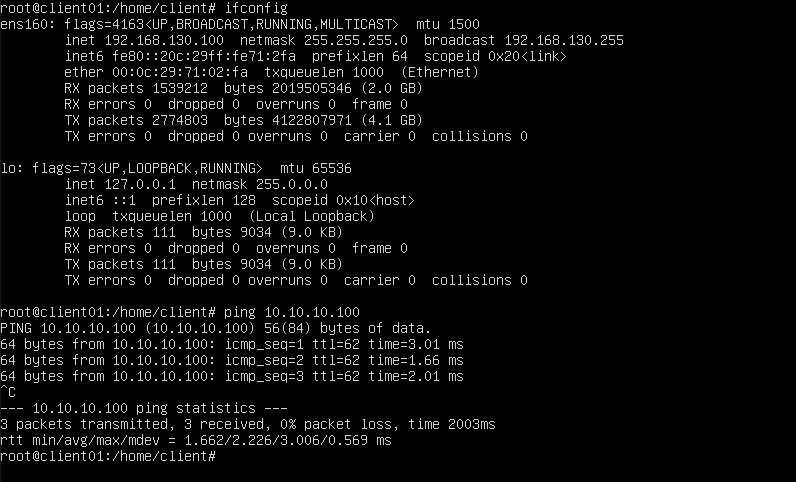
To test the configuration, the following screenshot shows a ping response of Madrid LAN client. Ottawa LAN client is pinging 10.10.10.100 which is then translated to remote IP of 192.168.130.100.
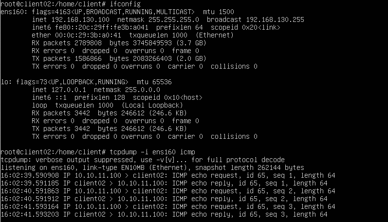
tcpdump output on Madrid LAN client confirms traffic received from action IP of Ottawa LAN client 10.10.11.100.